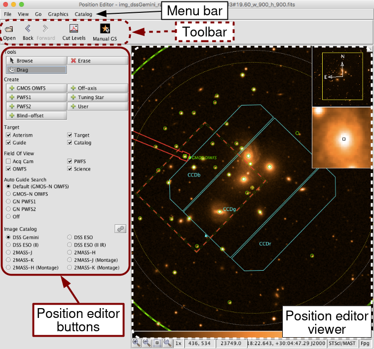
The position editor provides a graphical view of the observation and can interactively modify elements of it. The position editor is launched by clicking the Image button on the main toolbar or selecting "Show the Position Editor" from the View menu. It has four constituent parts, identified in the image below:
- Menu bar - open, save and print images; manipulate images and overlays; navigate through previously-viewed images; open on-line image, target catalogue and archive servers (including name resolution); open personal catalogues. See a detailed description of the menu bar functions.
- Toolbar - open stored images; navigate through previously-viewed images (also in the menu bar, see a description of the Go menu for history navigation info), change the display stretch, access the catalog viewer, and search for guidestars and download images. See a detailed description of the toolbar buttons.
- Position editor buttons - display or move the base position or instrument angle; display, add, move or delete WFS star or offset positions; display the WFS and science instrument fields of view and mosaic patterns; display guide star and on-line catalogue sources. See a detailed description of the position editor buttons.
- Position editor viewer - display an (optional) image of the field around the science target and overlay instrument, WFS and catalogue information. Any FITS image that contains a suitable world coordinate system may be used as the background image (see more details about the viewer). The viewer image (with or without overlays) can be printed or saved to disk (from the file and catalog items on the menu bar).
Buttons
The options in the Add, View, and AGS lists depend on the instrument component and whether an Adaptive Optics component has been included, so not all wavefront sensors, views, or AGS options may be available.
| Mode | Add | ||
 |
Browse | 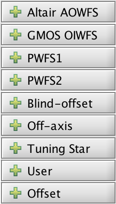 |
AOWFS |
| Drag | OIWFS | ||
| Erase | PWFS1 | ||
| PWFS2 | |||
| Targets | |||
| Offset | |||
| View | AGS | ||
 |
Base | 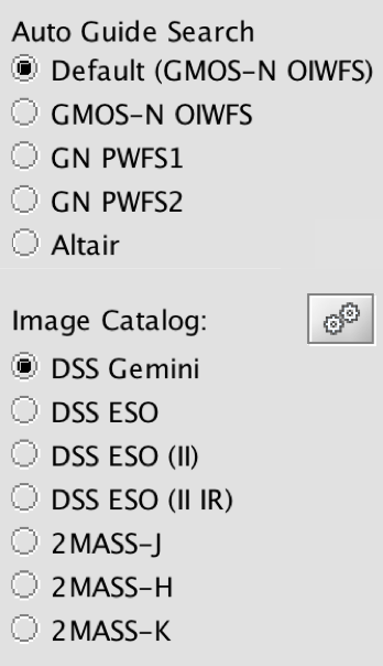 |
OIWFS |
| Guide | |||
| Target | PWFS | ||
| Catalog | |||
| Offset | AOWFS | ||
| Acq Cam | Images | ||
| AOWFS | |||
| OIWFS | |||
| PWFS | |||
| Science | |||
Mode: Browse
Moving the cursor over the position editor viewer displays the co-ordinate information at the bottom of the screen. You cannot drag or erase objects in the viewer (it is safe!). The normal cursor shape is unchanged (usually an arrow).
Mode: Drag
This mode is used to modify target coordinates and orientation. The cursor is hand-shaped when in this mode and positioned over an object that can be dragged.
With a base, WFS star or offset position displayed in the viewer you can click-and-drag the object to a new position. With the science field of view (sci area) displayed, click-and-drag it's handle to rotate the instrument position angle. The respective 'handles' to grab are:
| base - click and drag yellow 'earth' symbol | |
| PWFS1, PWFS2 or OIWFS - click and drag green box | |
| offset - click and drag (numbered) yellow circle | |
| position angle - click and drag blue triangle |
The base position may often be obscured by the offset sequence. If this is the case, deselect the offset view. The NIRI f/6 camera and the acquisition camera have a very similar field of view; you may need to deselect the acquisition camera view to see the NIRI science field.
![]() Moving these objects changes their coordinates in the telescope (base, WFS), offset sequence iterator (offsets) or instrument (position angle) components of your Science Program. The new co-ordinates are derived from the background image so beware when moving WFS probes that require the astrometric accuracy of a guide star catalog.
Moving these objects changes their coordinates in the telescope (base, WFS), offset sequence iterator (offsets) or instrument (position angle) components of your Science Program. The new co-ordinates are derived from the background image so beware when moving WFS probes that require the astrometric accuracy of a guide star catalog.
When the base position is moved, other relevant parameters (e.g. WFS patrol field of view, offset sequences) will also move
Mode: Erase
This mode is used to delete offset or WFS positions. The cursor is I-shaped when in this mode and positioned over an object that can be deleted.
With the WFS or offset positions displayed in the viewer, position the cursor over the object 'handle' and click to delete (see drag mode for the handles). Holding down the left mouse down and 'wiping' the cursor like an eraser is also effective. Deleting objects from the viewer also deletes them from the telescope targets component or offset sequence iterator.
Offset and WFS positions can also be deleted using the offset iterator and target components in the Science Program.
Add: PWFS1
Clicking on the image takes the (+ shaped) cursor co-ordinates and adds them to the target list in the Science Program target component. If the image is overlayed with a catalog (e.g. of guide stars) then the coordinates are taken from the catalog and do not rely on the accuracy of the image co-ordinates. In the latter case, the cursor need not be positioned precisely, within the square catalog overlay box is sufficient:
| co-ordinates taken from image because star not in catalog (and thus relies on image co-ordinate system accuracy) | |
| co-ordinates taken from catalog because cursor is inside catalog overlay box |
The coordinates are assigned a tag that associates them with Peripheral Wavefront Sensor #1, i.e. PWFS1 (n) where n is a unique integer. Multiple positions can be associated with each wavefront sensor if different guide stars are required to execute a particular dither/mosaic pattern (use the offset iterator to assign WFS stars to offset positions). If the view PWFS1 button is selected (this occurs automatically when add PWFS1 is selected) then a green box is drawn at the the target location and is labelled with the tag ID.
![]() If the guide star is chosen manually using this button there is no checking that it will be sufficiently bright for the selected WFS and conditions, and it is therefore highly recommended that guide stars are selected via the Auto GS button instead.
If the guide star is chosen manually using this button there is no checking that it will be sufficiently bright for the selected WFS and conditions, and it is therefore highly recommended that guide stars are selected via the Auto GS button instead.
If at any offset position the guide star is not reachable (i.e. is outside the yellow dashed circle) there will be a Problem flagged with a red X: "The PWFS1 guide star falls out of the range of the guide probe field at one or more offset positions." This problem may be resolved either by selecting a different guide star within the green circle, or by moving the unreachable offset position closer to the guide star after inspecting the the WFS and sci area fields of view.
If at any offset position the guide probe may vignette the science field of view there will be a Problem flagged with a yellow warning symbol: "The PWFS1 guide star falls inside the recommended radius at one or more offset positions an may cause vignetting." This may be resolved either by selecting a different guide star farther from the Base position, or by moving the offending offset position farther from the guide star after inspecting the the WFS and sci area fields of view.
Add: PWFS2
Clicking on the image takes the (+ shaped) cursor co-ordinates and adds them to the target list in the Science Program target component. If the image is overlayed with a catalogue (e.g. of guide stars) then the coordinates are taken from the catalog and do not rely on the accuracy of the image coordinates. In the latter case, the cursor need not be positioned precisely, within the square catalog overlay box is sufficient:
| co-ordinates taken from image because star not in catalog (and thus relies on image co-ordinate system accuracy) | |
| co-ordinates taken from catalog because cursor is inside catalog overlay box |
The coordinates are assigned a tag that associates them with Peripheral Wavefront Sensor #2, i.e. PWFS2 (n) where n is a unique integer. Multiple positions can be associated with each wavefront sensor if different guide stars are required to execute a particular dither/mosaic pattern (use the offset iterator to assign WFS stars to offset positions). If the view PWFS2 button is selected (this occurs automatically when add PWFS2 is selected) then a green box is drawn at the the target location and is labelled with the tag ID.
![]() If the guide star is chosen manually using this button there is no checking that it will be sufficiently bright for the selected WFS and conditions, and it is therefore highly recommended that guide stars are selected via the Auto GS button instead.
If the guide star is chosen manually using this button there is no checking that it will be sufficiently bright for the selected WFS and conditions, and it is therefore highly recommended that guide stars are selected via the Auto GS button instead.
If at any offset position the guide star is not reachable (i.e. is outside the yellow dashed circle) there will be a Problem flagged with a red X: "The PWFS2 guide star falls out of the range of the guide probe field at one or more offset positions." This problem may be resolved either by selecting a different guide star within the green circle, or by moving the unreachable offset position closer to the guide star after inspecting the the WFS and sci area fields of view.
If at any offset position the guide probe may vignette the science field of view there will be a Problem flagged with a yellow warning symbol: "The PWFS2 guide star falls inside the recommended radius at one or more offset positions an may cause vignetting." This may be resolved either by selecting a different guide star farther from the Base position, or by moving the offending offset position farther from the guide star after inspecting the the WFS and sci area fields of view.
Add: Inst OIWFS
Clicking on the image takes the (+ shaped) cursor co-ordinates and adds them to the target list in the Science Program target component. If the image is overlayed with a catalogue (e.g. of guide stars) then the coordinates are taken from the catalog and do not rely on the accuracy of the image co-ordinates. In the latter case, the cursor need not be positioned precisely, within the square catalog overlay box is sufficient:
| co-ordinates taken from image because star not in catalog (and thus relies on image co-ordinate system accuracy) | |
| co-ordinates taken from catalogue because cursor is inside catalog overlay box |
The coordinates are assigned a tag that associates them with the On-Instrument Wavefront Sensor, i.e. Inst OIWFS (n) where n is a unique integer. Multiple positions can be associated with each wavefront sensor if different guide stars are required to execute a particular dither/mosaic pattern (use the offset iterator to assign WFS stars to offset positions). If the view OIWFS button is selected (this occurs automatically when add OIWFS is selected) then a green box is drawn at the the target location and is labelled with the tag ID.
![]() If the guide star is chosen manually using this button there is no checking that it will be sufficiently bright for the selected WFS and conditions, and it is therefore highly recommended that guide stars are selected via the Auto GS button instead.
If the guide star is chosen manually using this button there is no checking that it will be sufficiently bright for the selected WFS and conditions, and it is therefore highly recommended that guide stars are selected via the Auto GS button instead.
If at any offset position the guide star is not reachable (i.e. is outside the red dashed box) there will be a Problem flagged with a red X: "The OIWFS guide star falls out of the range of the guide probe field at one or more offset positions." This problem may be resolved either by selecting a different guide star within the green box, or by moving the unreachable offset position closer to the guide star after inspecting the the WFS and sci area fields of view.
Add: AOWFS
Clicking on the image takes the (+ shaped) cursor co-ordinates and adds them to the target list in the Science Program target component. If the image is overlayed with a catalog (e.g. of guide stars) then the coordinates are taken from the catalog and do not rely on the accuracy of the image coordinates. In the latter case, the cursor need not be positioned precisely, within the square catalog overlay box is sufficient:
| co-ordinates taken from image because star not in catalog (and thus relies on image co-ordinate system accuracy) | |
| co-ordinates taken from catalog because cursor is inside catalog overlay box |
The coordinates are assigned a tag that associates them with the Adaptive Optics Wavefront Sensor, i.e. AOWFS (n) where n is a unique integer. Multiple positions (tags) can be associated with the wavefront sensor although only one can be used for any individual observation (use the Altair Adaptive Optics component [FIX LINK] to assign which WFS tag to use). If the view AOWFS button is selected (this occurs automatically when add AOWFS is selected) then a green box is drawn at the the target location and is labelled with the tag ID.
![]() At present there is no checking that the selected AOWFS star is within the Altair patrol field. You should display the WFS and sci area fields of view to confirm this visually. There is no checking that the selected star is sufficiently bright for the selected WFS.
At present there is no checking that the selected AOWFS star is within the Altair patrol field. You should display the WFS and sci area fields of view to confirm this visually. There is no checking that the selected star is sufficiently bright for the selected WFS.
Add: Targets
These four buttons allow you to add different kinds of off-axis targets to the list of targets in the Target Component. Clicking on the image will add the location of the (+ shaped) cursor or the object at that location. If the image is overlayed with a catalog (e.g. of guide stars) then the coordinates are taken from the catalog and do not rely on the accuracy of the image coordinates. In the latter case, the cursor need not be positioned precisely, within the catalog marker is sufficient, just as with selecting guide stars. A manual guide star search will overlay the objects from the selected catalog. The uses of the different target types are:
- Blind-offset: A star or bright, compact source to be used for blind-offset acquisitions.
- Off-axis: Any target that does not sit at the Base position. This object should be placed in the desired instrument aperture.
- Tuning Star: A nearby star to be used for tuning the telescope optics before open-loop LGS observations [FIX LINK].
- User: A generic target position, for backwards compatibility.
Add: Offset
Clicking on the image adds the location of the (+ shaped) cursor to the list of offsets in the offset sequence iterator. The offset is the difference in arcsec between the cursor and base positions in the (p,q) co-ordinate frame (see the iterator page for more details on p,q co-ords).
If the view offset button is selected, the viewer shows the new offset (as a yellow circle) optionally labelled with the offset list tag number and the science area. The offset display is configured from the view offset display item on the menu bar.
![]() This button will not be displayed if there is no offset iterator in the observation.
This button will not be displayed if there is no offset iterator in the observation.
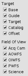
View: Base
Displays the base position (as a yellow earth symbol; can be hard to see against a bright object) taken from the target component. With view base selected, the view offset button shows any science instrument offset positions that are defined in the offset sequence iterator.
![]() This button will not be displayed in the unlikely event that there is no target component in the observation.
This button will not be displayed in the unlikely event that there is no target component in the observation.
View: Guide
Displays any PWFS or OIWFS co-ordinates and tags contained in the target component.
View: Target
Display any User, Blind-offset, Off-axis, or Tuning Star positions in the target component.
View: Catalog
Displays objects from any catalog (e.g. of guide stars) that has been loaded. If several catalogs have been loaded, all objects are displayed. Use the catalog navigator, opened from the catalog browse item in the menu bar, to manipulate the display of multiple catalogs.
View: Offset
Displays any offset positions defined in the the offset iterator. The view base button must also be selected to see the science instrument offsets.
The offset display is configured from the view offset display item on the menu bar. You can choose whether to display the offset sequence tags and the science area at the position selected in the offset list, none or all positions. The science field of view at the currently selected offset position (in the offset iterator list) is displayed in the Position Editor viewer in yellow. (The science field of view at the base position is shown in blue).
View: PWFS
Displays the outer patrol field (as large concentric circles) and vignetting pattern of the Peripheral Wavefront Sensors. The two PWFSs are part of the acquisition and guidance unit and their pick-off probes can be swung into the beam upstream of the science instruments and the acquisition camera. The diameter of their outer patrol field is about 14 arcmin (to be confirmed; see more details). The probe arms are mounted on rotary tables and can reach any part of the field.
The position editor viewer contains a model of the PWFSs and their rotary tables. If the PWFS FOV view is selected and you drag the PWFS or the base position, then the probe arms attempt to follow the motion.
![]() The location of the PWFS vignetting pattern and patrol field depends on the offset position selected in the offset iterator table. If the WFS is assigned to a guide star, the vignetting overlay moves for each position in the offset sequence as the probe moves to remain pointing at the same RA,dec. The patrol field overlay also moves, corresponding to the new telescope pointing position. If the PWFS is "frozen" for that offset step, then it's orientation with respect to the patrol field and detector is kept fixed. You can use the offset iterator table for a simple 'playback' of the whole sequence.
The location of the PWFS vignetting pattern and patrol field depends on the offset position selected in the offset iterator table. If the WFS is assigned to a guide star, the vignetting overlay moves for each position in the offset sequence as the probe moves to remain pointing at the same RA,dec. The patrol field overlay also moves, corresponding to the new telescope pointing position. If the PWFS is "frozen" for that offset step, then it's orientation with respect to the patrol field and detector is kept fixed. You can use the offset iterator table for a simple 'playback' of the whole sequence.
![]() As the probe arms are nested one above the other, PWFS1 may vignette PWFS2 and both may vignette the science field. The PWFSs are situated about 1.5m above the telescope focal plane and so are out of focus as seen by the science instrument. The position editor viewer shows the vignetting in the telescope focal plane as well as the vignetting at the level of the PWFS. Since the probe arms are out of focus, the vignetting in the telescope focal plane varies from zero at the outer edge of the lightly shaded region to 100% at the inner edge and throughout the heavily shaded region.
As the probe arms are nested one above the other, PWFS1 may vignette PWFS2 and both may vignette the science field. The PWFSs are situated about 1.5m above the telescope focal plane and so are out of focus as seen by the science instrument. The position editor viewer shows the vignetting in the telescope focal plane as well as the vignetting at the level of the PWFS. Since the probe arms are out of focus, the vignetting in the telescope focal plane varies from zero at the outer edge of the lightly shaded region to 100% at the inner edge and throughout the heavily shaded region.
![]() If the guide star is chosen manually there is no checking that it will be sufficiently bright for the selected WFS and conditions, and it is therefore highly recommended that guide stars are selected via the Auto GS button instead.
If the guide star is chosen manually there is no checking that it will be sufficiently bright for the selected WFS and conditions, and it is therefore highly recommended that guide stars are selected via the Auto GS button instead.
If at any offset position the guide star is not reachable (i.e. is outside the yellow dashed circle) there will be a Problem flagged with a red X: "The PWFS guide star falls out of the range of the guide probe field at one or more offset positions." This problem may be resolved either by selecting a different guide star within the green circle, or by moving the unreachable offset position closer to the guide star.
If at any offset position the guide probe may vignette the science field of view there will be a Problem flagged with a yellow warning symbol: "The PWFS guide star falls inside the recommended radius at one or more offset positions an may cause vignetting." This may be resolved either by selecting a different guide star farther from the Base position, or by moving the offending offset position farther from the guide star.
When chopping and nodding, the PWFS is used in the 'main' beam corresponding to Nod A Chop A (and Nod B Chop B, since the nod is currently required to be equal in amplitude and opposite in direction to the chop). The location of the PWFS probe at the other two positions on the sky (Nod A Chop B and Nod B Chop A) can be displayed by toggling the View, PWFS FOV Display menu items.
View: OIWFS
Displays the patrol field of the On-Instrument Wavefront Sensor (if the instrument has one). See the relevant instrument's pages [FIX LINK] for details of the specific vignetting pattern (under the performance and use section elements of [instrument]).
The OIWFS view is configured from the view OIWFS FOV display item on the menu bar. You can choose whether to display the vignetting region in outline or solid block of colour. If the OIWFS is not in the focal plane (e.g. NIRI) you can choose whether to include or exclude the partially vignetted region.
As it is part of the instrument the OIWFS patrol field rotates with the science field.
![]() The location of the OIWFS vignetting pattern and patrol field depends on the offset position selected in the offset iterator table. If the OIWFS is assigned to a guide star, the vignetting overlay moves for each position in the offset sequence as the probe moves to remain pointing at the same RA, dec. The patrol field overlay also moves, corresponding to the new telescope pointing position. If the OIWFS is "frozen" for that offset step, then it's orientation with respect to the patrol field and detector is kept fixed. You can use the offset iterator table for a simple 'playback' of the whole sequence.
The location of the OIWFS vignetting pattern and patrol field depends on the offset position selected in the offset iterator table. If the OIWFS is assigned to a guide star, the vignetting overlay moves for each position in the offset sequence as the probe moves to remain pointing at the same RA, dec. The patrol field overlay also moves, corresponding to the new telescope pointing position. If the OIWFS is "frozen" for that offset step, then it's orientation with respect to the patrol field and detector is kept fixed. You can use the offset iterator table for a simple 'playback' of the whole sequence.
![]() If the guide star is chosen manually there is no checking that it will be sufficiently bright for the selected conditions, and it is therefore highly recommended that guide stars are selected via the Auto GS button instead.
If the guide star is chosen manually there is no checking that it will be sufficiently bright for the selected conditions, and it is therefore highly recommended that guide stars are selected via the Auto GS button instead.
If at any offset position the guide star is not reachable there will be a Problem flagged with a red X: "The OIWFS guide star falls out of the range of the guide probe field at one or more offset positions." This problem may be resolved either by selecting a different guide star or by moving the unreachable offset position closer to the guide star.
View: AOWFS
Displays the patrol field of the Altair Adaptive Optics Wavefront Sensor.
![]() The location of the AOWFS patrol field depends on the offset position selected in the offset iterator table. If the AOWFS is assigned to a guide star, the patrol field overlay moves, corresponding to the new telescope pointing position. If the AOWFS is "frozen" for that offset step, then it's orientation with respect to the patrol field and detector is kept fixed. You can use the offset iterator table for a simple 'playback' of the whole sequence.
The location of the AOWFS patrol field depends on the offset position selected in the offset iterator table. If the AOWFS is assigned to a guide star, the patrol field overlay moves, corresponding to the new telescope pointing position. If the AOWFS is "frozen" for that offset step, then it's orientation with respect to the patrol field and detector is kept fixed. You can use the offset iterator table for a simple 'playback' of the whole sequence.
![]() At present there is no automatic checking that the guide star is within the AOWFS patrol field. There is no checking that the selected star is sufficiently bright for the AOWFS.
At present there is no automatic checking that the guide star is within the AOWFS patrol field. There is no checking that the selected star is sufficiently bright for the AOWFS.
View: Science
Displays the science instrument's field of view. The FOV depends on the instrument configuration defined in the Science Program instrument component. For example, the science field changes for different NIRI cameras, becomes a slit in spectroscopic modes etc. See the science instrument component for configuration details.
The science field of view at the base position is displayed in the Position Editor viewer in blue. (The science field of view at the currently selected offset position, in the offset iterator list, is shown in yellow).
View: Acq Cam
Displays the 2 x 2 arcmin field of view of the acquisition camera. The AcqCam FOV is fixed in the telescope focal plane and rotates with the science field.
View: Automatic Guide Star Options
These radio buttons toggle the guider which will be used for the Automatic Guide star algorithm.
![]() Only the available guiders are displayed, so this list will look different for each instrument and whether an Adaptive Optics component has been included.
Only the available guiders are displayed, so this list will look different for each instrument and whether an Adaptive Optics component has been included.
View: Image Catalog Options
These radio buttons toggle the image server that will be used to display the image of the field. The OT will automatically download and cache images of each observation in the displayed programs that do not have observation statuses of Observed or Inactive. By default the DSS servers at Gemini are queried, but the server can be chosen using the radio buttons. The choice will be remembered.
The images are cached locally so that they will be reused when the OT is started again. The cache can be controlled by clicking the  icon in the Position Editor or by selecting Preferences in the Edit menu of the Science Program Editor.
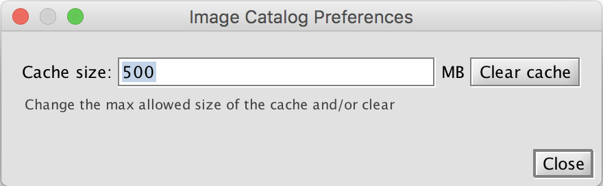
The cache size limit in megabytes is set in the entry box. Once the cache size exceeds this limit then images are deleted in reverse order of when they were last accessed (recently accessed images are retained). All images in the cache can be deleted by clicking the "Clear cache" button.
Menu Bar
The position editor menu bar is used to configure the image and overlay displays:
- File - open, save and print images (see details below).
- View - configure and examine the image properties (including cut levels, colour table and FITS header; see below); configure the offset and WFS displays (see details below).
- Go - navigate the image history list
- Graphics - annotate the image with text and graphics. These can be saved with the underlying image
- Catalog - change internet proxy settings, pick an object, and access the catalog query tool. The overlays can be saved with the underlying image.
Further information about the highlighted functions see below.
Open, Save and Print Images
Any simple FITS image may be loaded into the position editor. If the image has multiple planes, a summary of the image extensions is reported and you can choose which extension to display.
The raw image can be saved to a FITS file or in one of several file formats (e.g. jpeg, tiff, bitmap) from the file save as menu. You can save any graphics (overlays, annotations) as an extension in the FITS file using the graphics save graphics with image menu. Likewise you can save catalogs in a FITS extension using the catalog...save catalog overlays with image menu. This FITS file may be loaded into the position editor at a later time, the image displayed and extensions selected and displayed using the manipulation tools.
Alternatively, and more portably, you can save the overlays along with the image in jpeg or gif formats from the file save current view menu. This format is particularly useful if you have annotated the image e.g., as a finding chart.
The image with overlays can be printed, and previewed, directly from within the position editor or by printing an image saved to disk.
To close the position editor select file close or click on the X in the upper right corner.
Image Examination and Manipulation
You can interactively change the high and low cut levels either manually, by selecting the percentile range or the median clipped range from the view cut levels menu.
You can change the colour table, intensity transformation and mapping algorithm from and view colors menu.
The view fits extensions menu shows the various data structures contained in the FITS file. This may simply be the image plane or may include header and data extensions. If you have used the position editor to save an image with a catalog then select the appropriate FITS table extension name and click open. This opens the catalog navigator from which you can plot (or unplot) the catalogued objects.
The keywords, values and comments in the current FITS header are displayed with the view fits keywords menu.
Configure the Offset Display
The view base position offset display menu configures how the offset iterator sequence is displayed. You can toggle the tags (steps in the offset list) on/off, and display the science field of view at the selected, all or none of the offset positions.
Configure the OIWFS FOV Display
From the view OIWFS FOV display menu you can choose whether to display the on-instrument wavefront sensor vignetting region in outline or solid block of colour. If the OIWFS is not in the focal plane (e.g. NIRI) you can choose whether to include or exclude the partially vignetted region.
History List
The position editor maintains a history list of images displayed. You can navigate forwards or backwards through the list, jump to a particular image, or clear the history list from items in the Go menu.
Proxy Settings and Catalog Objects
If your computer is behind a firewall with a proxy server, then enter the server details in the Proxy Server dialog. This may be needed to access catalog and image servers on the internet.
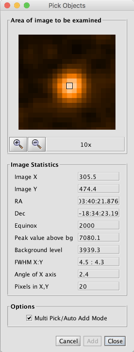
The Pick Objects dialog is used for zooming in and selecting an individual object. The selected object will be added as a User target to the currently selected observation.
The Manual GS catalog menu option opens the Catalog Query Tool for querying guide star catalogs and manually selecting a star.
Toolbar
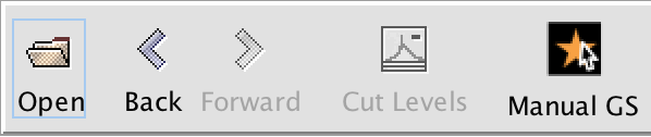
The Position Editor Toolbar provides quick access to the most commonly used features from the menu bar. The buttons have the following action:
- Open - bring up a file selection dialog to load a previously saved image.
- Back - move backwards in image history list.
- Forward - move forward in image history list.
- Cut levels - bring up a dialog of showing the distribution of pixel values for the displayed image. The minimum and maximum display levels can be set either with the slider or the Auto Set buttons.
- Images - queries the the default image server using the base coordinates of the observation selected in the Program Editor. The default can be changed by selecting a new server from Catalog -> Image Servers in the menu bar (the current default is marked with a black dot).
- Manual GS - opens the Catalog Query Tool or the GeMS Guide Star Search Tool (GeMS observations only) for doing quick guide star searches. The coordinates for the search is the base position of the observation selected in the Program Editor. Likewise the Instrument is set using the instrument component of the selected observation in the Program Editor. The Guide Star Type and the Catalog is remembered from the last query. The combination of the instrument and guide star type determine the minimum and maximum radii and the limiting magnitude for the query.
If a position angle of PA ± 180 degrees is acceptable for your observations, then select "Allow 180 flip" in the instrument component:
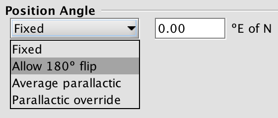
With this option permitted the guide star selection will automatically change the PA if a brighter guide star is available at PA ± 180 degrees.
If no guide star is available at the current PA or PA ± 180 and PA is not important for your observations, then you should check if a guide star is available at another PA. All guide stars that are usable with the current conditions constraints are marked with red circles on the Position Editor and can be quickly selected with the + GMOS/FII OIWFS PE button.
Viewer
The Position Editor Viewer can display an image of the field an overlay it with information about the observation. It is not necessary to have a background image in orderto show the overlays. The overlays can be toggle and manipulated using the position editor buttons. The image can be manipulated using the view item on the menu bar.
Additional features of the viewer are:
- Zoom buttons (+,-) and current magnification shown on the lower status bar (also available in the position editor menu bar).
- Pixel coordinates and value for the current cursor position shown on the lower status bar.
- RA, dec and co-ordinate system (e.g. J2000) for the current cursor position derived from the image world co-ordinate system information.
- Pan and (fixed-magnification) zoomed windows show in the upper riight. The yellow box in the pan window shows the area currently displayed in the main window. Click-and-drag the yellow box to pan around the field at the current magnification. Display of the pan and magnifier window may be toggled using the hide button.
- Measure distances between two positions by right-clicking-and-dragging the cursor. The separations are given in arcmin:arcsec in both RA, dec axes and along the hypotenuse.
By default the image and overlays displayed correspond to the currectly selectedobservation in the science program. You can navigate through other, previously stored, images using the position editor toolbar (and get very confused!). A warning is shown in the viewer if the base (telescope pointing) position is outside of the displayed field.
Image Cache Details
The position editor viewer maintains a cache of 20 images. Whenever you select an observation in the science program, the software looks for an image in the cache whose center is close to the base position and displays it, if it is found. This means that if you move the base position a certain amount, the image in the cache will not be used any more.
The files in the cache directory correspond to the files in the image history menu (go item on the menu bar). The latest files are always shown at the top of the menu and when more than the maximum number (currently 20) is reached, the oldest image file is deleted and removed from the end of the menu.
The cache directory can be found at $HOME/.jsky/cache. Under windows $HOME is what ever is returned by java for the 'user-home' property. For Windows 2000, this is Documents andSettings\