 |
Near-IR Integral Field Spectrograph (NIFS) in the
Observing Tool
|
Like all Gemini facility instruments, NIFS is operated through
the Gemini observing tool (OT). A proper NIFS phase II proposal should
specifiy the observations to be taken in detail, just as if they were
being executed at the telescope. The best way to create a phase II
proposal is to start with the NIFS phase II OT-Library of predefined observing
sequences. This will ensure that many of the details are automatically
taken care of. Once familiar with these default sequences, the observer
can modify them as desired.
NIFS OT basics
If you are
unfamiliar with the OT for NIFS, then the following
information will introduce you to the basics. If you are familiar with
the NIFS OT, then you might jump to the next section and start defining
your phase II proposal. Basic information on the OT itself is available
here.
NIFS
observations are specified in a hierarchy of components:
- NIFS Component -
to define the
basic configuration of the instrument
- Altair AO
Component - to
choose
and configure Altair for adaptive optics coupled with NIFS
- NIFS Sequence
Iterator - to
sequence different configurations, for example, to cycle the
observation through multiple grating settings
Beyond properly configuring NIFS, it is also important to specify guide stars for Altair
and
possibly the peripheral wavefront sensor (PWFS2) or on-instrument
wavefront sensor (OIWFS).
Refer to the NIFS
instrument
pages to see how best to use the instrument. See the NIFS
checklist to verify the completed phase II proposal includes all
the items a PI needs to consider. |
NIFS predefined
observing sequences
The easiest way
to develop the Phase II proposal is to use the
predefined observations in the NIFS OT Library. These sequences cover
the basic observations that most programs will use. The best practice is
to use (or at least review) the library version for
the current observing semester. This way, updates or changes to NIFS
observation protocols will automatically be accounted for in new Phase
II proposals. Detailed
notes and descriptions appear directly in the library sequences to help
observers understand how to use NIFS.
Phase II submissions for NIFS and for NIFS+ALTAIR are required to
contain acquisition sequences and all calibrations (flats, arcs, and
telluric standard stars). Examples of observations grouped with these calibrations
included are given in the NIFS OT Library. |
NIFS Component
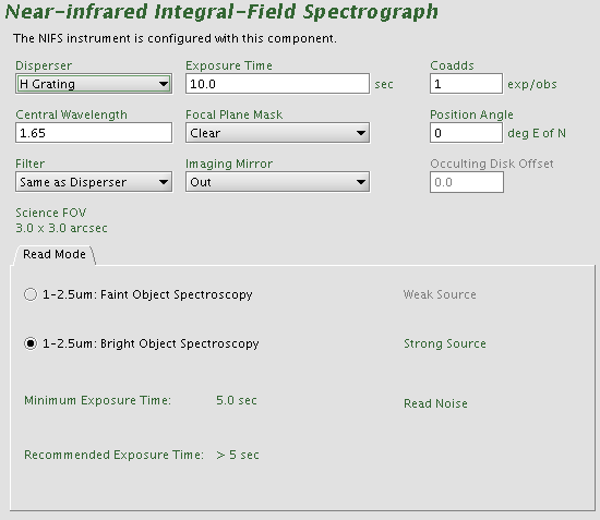
The detailed component editor for NIFS is accessed in the usual
manner, by selecting
the NIFS component in the science program, and is shown below:
Selecting a grating, filter,
and focal plane mask
Typically, the grating for the observation is chosen first. Then the
default central wavelength will automatically be entered into the NIFS
component. NIFS covers essentially all of the associated photometric
band in one shot, and the default settings are designed for this case.
If the filter is chosen as "Same as Disperser," then the appropriate
default blocking filter is selected at the time of observation.
The focal plane mask should be "clear" for regular observations.
Several focal plane occulting masks are available for observations of
bright targets with faint companions. An "imaging mirror" may be
selected for acquistion; chose "in" for this case, otherwise "out.".
NIFS has four gratings physically mounted in the dewar. Each default
configuration of grating choice uses a dual blocking filter, one of
Z-J, J-H, or H-K for Z and J, H, and K gratings, respectively. The
following table explains the proper combinations:
| Grating
Name |
Default Filter
|
Central Wavelength (microns)
|
| Z |
ZJ |
1.05
|
| J |
ZJ |
1.25
|
| H |
JH |
1.65
|
| K |
HK |
2.20
|
K
|
K
+ wire grid
|
2.20
|
The instrument can be configured to modify these default grating
settings by choosing a different central wavelength. This should not be
necessary for most programs, however, at least three addtional
possibilities may be useful. One is to rotate the grating turret to
shorter K band wavelengths to observe further into the telluric band
near 1.9 um. Paschen alpha, for example, can be observed from Mauna Kea
on dry nights. Similarly, one can observe at longer K band wavelengths.
The third is to specify the K band filter plus wire grid for
polarimetry mode (this is a different special filter with the wire grid
built in).
Controlling the exposure
The exposure time is set by clicking in the dialog box and
typing the required
number of seconds. Each occurrence of the observe
element will cause N exposures to be taken and coadded in
the instrument
control system resulting in a single image written to disk. The value
of N is set by typing an integer in
the
"coadds" window. The total integration time in each output image will be the
"Exposure Time"
times the number of coadds.
Setting the position angle
The facility Cassegrain Rotator can rotate the instrument to any
desired position angle. The
angle (in conventional astronomical notation of degrees east of north)
is set by typing in
the "position angle" box. The view of the science field in the
position
editor will reflect the selected angle. Alternatively the angle may
be
set or adjusted in
the position editor itself by interactively rotating
the science field.
Array readout mode
Choose either bright or faint object mode. Objects fainter than
about K~10 should use the faint object mode. The array chacteristics given
in green at the bottom of the OT screen will get updated when a different readmode is selected.
Altair AO Component
This component
must be included in the observation only if NIFS is to be
used with Altair.
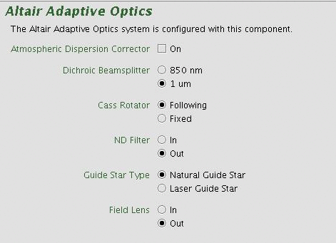
The component allows the observer to choose 0.85 um and 1 um dichroics
for Altair. The 1 um dichroic should be used for JHK-band observations
and 0.85mu dichroic should be selected for Z-band
observations.
Observers should choose the default "following" for the Cass Rotator to
take out field rotation and keep objects fixed on the NIFS detector.
Future releases of the OT should include a selection for the
Altair field lens.
For now, observers should specify use of the field lens in an OT "Note"
component. Normally, the field lens would not be needed with NIFS since
it is intended to increase the field over which the Altair correction
is effective (high Strehl). Since the NIFS field is small, there is no
need to use the field lens. However, the corrected field will impact
the use of the OIWFS if the OIWFS guide star is far off axis (>25
arcsec), and depending on the expected observing conditions (seeing).
In this case, it may be necessary to use the field lens (
see below).
The use of the laser guide star (LGS) is not yet specified in the OT.
NIFS Iterator Component
The NIFS Sequence Iterator is a member of a class of instrument
iterators.
Each works exactly the same way, except that different
options are
presented depending upon the instrument. Use this component to change
the instrument configuration during the observation, for example, to
repeat the same basic observation at two grating settings. For
observations that take a significant amount of time (approximately
greater than 1
hr) iterating the instrument configuration between multiple gratings is
not a good idea. This is
because observing conditions may change, calibrations need to be
taken, or the queue operator will only have limited time on any given
night to complete part of the observation. In this case, break up NIFS
observation into a separate "Observation" and best practice is to cut
and
paste your observations and change the instrument configuration for
each separate observation. This allows for more flexibility at the
telescope. Short observations of bright targets are good candidates for
an instrument configuration iterator.
Below we see a few of the iterator features in the right panel of
the OT tool
(the left panel shows multiple observations in the NIFS Library with
the details of observation 1 shown):
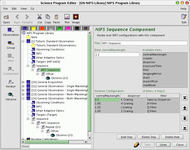
An iteration sequence ("NIFS Sequence" in the above image) is set by choosing "NIFS Sequence" from the "iterator" menu.
The table
columns in the "NIFS Sequence Component" are items over which to iterate.
In this example we are
iterating over gratings (and hence filters and central wavelengths
which are not set automatically in this component) so there are three
corresponding columns in the table.
Table rows correspond
to iterator steps. At run time, all the values in a row are set at
once. Since there are four NIFS configuration steps in this observation
and an offset iterator below (in this case with a five-point dither) an
"observe" element would
produce an observe command for each of four grating setups times the
number of offsets (five), using the
specified integration
time, focal plane mask, etc. specified in the main NIFS component:

In the above figure, the iteration table shows parts of observe 4,
5, and 6 (of 20 total). The first five exposures are taken with the
step 1 configuration (in this case the K grating) with the telescope
dithering before each exposure (p, q offsets). After step 5, the
instrument is
re-configured with the H grating for the next five offset exposures.
Rows or columns may be added and removed at will. Rows (iteration
steps) may be
rearranged using the arrow buttons. Rows will be added or removed by
clicking "Ad Step" or "Delete Step" buttons, and columns can be deleted
by clicking "Delete Item". Adding column can be done by selecting one
from the "Available Items" box.
Specifying AOWFS Stars and Guide
Stars for NIFS
The Altair "AOWFS" star is specified in the targets section of the main
observation as shown below. For on-source correction of the wavefront,
the coordinates of the AOWFS star should be identical to the target
coordinates (the Dist field should show "0").
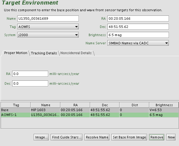
Information for the base position (i.e. the science object) and guide
star(s) may be editied by clicking the appropriate line in the target
table at the bottom and then editing the various fields through the
text boxes above. Changing the type of target may be done using
the "tag" pull down menu at the upper left.
Details on how to add guide stars (of any type) can be found in the
OT Tutorial. Guide stars
can be added (click "new") or deleted (click "remove") manually. A
better way to define guide stars is to use the position editor to query an image of the field
and add stars interactively from the on-line catalogs. The USNO catalog
and 2MASS catalog give accurate positions for visible and near infrared
sources.
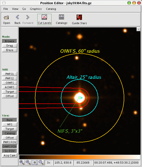
An example image field is shown below (from the position editor) with the
science field (small green box) and WFS fields overlayed (blue and
yellow circles). The NIFS pickoff probe is outlined as well in red. The
yellow circle is the OIWFS field and the blue one is the useful Altair
field for wavefront correction. Since the AO fold mirror in the
Cassegrain instrument cluster first sends the telescope beam to Altair,
the Altair field is unvignetted. The NIFS science field pick off will
vignette the OIWFS field as shown. The Cassegrain rotator may be
adjusted (position angle) to access OIWFS guide stars which would
otherwise be vignetted.
Things to remember or consider for choosing suitable NIFS guides stars:
- All observations must have a guide star. This will usually
include at least an AOWFS star.
- AOWFS stars should be as bright and close to the target as
possible, and no further than 25'' away. See the Altair Perfomance
and Use page. Full correction requires a WFS star with R<11;
partial correction can be achieved with stars as faint as R ~ 14.5
(on-axis).
- Always make sure to check that the selected observing conditions
for cloud cover (CC) are consistent with the guide star brightness.
- The OIWFS can be used in combination with the AOWFS star for long
observations where flexure between NIFS and Altair might be important.
This mode may also help with precise re-centering of the science field
following telescope motions (e.g. after a large offset and when a focal
plane mask is being used). Performance of the OIWFS will depend on the
distance to the guide star from the AOWFS star since the entire field
is corrected by Altair and the effects of anisoplanatism will degrade
the image quality at large distances. OIWFS stars should be roughly
K<14, and commissioning experience shows that OIWFS stars can be as
far away as 48 arcsec (without resorting to the field lens).
- It is possible to use NIFS without Altair. In excellent seeing,
if no guide star is available for Altair, one could consider using the
PWFS2. In this case, the "Altair Component" in the main observation
should be deleted.
![[Science Operations home]](../generic-images/sciopshomebtn.gif)
![[Observing Tool home]](othomebtn.gif)
Last
update: 2006 February 7, B. Miller
Previous version: 2005 November 22; R.Blum, T. Beck, I. Song
Original page created, 2005 November
18; R. Blum


