Observation preparation
This section focuses on how to prepare NIRI observations for your Phase I and Phase II submissions. Preparing observing sequences involves much more than setting up the observation of the target; the complete observing sequences must include in addition "acquisition observations" (e.g., for finding the target and centering it on the image ) if needed, observations of telluric standards and/or flux standards, and usually includes flat field calibrations and dark frames.
Overheads
Acquisition overheads associated with setting up on each new science target include time for slewing the telescope, configuring the instrument and WFS, and in the case of (archival) spectroscopic observations, centering the target in a slit.
OT Details
The instrument non-specific aspects of the Observing Tool (OT) are described elsewhere. Detailed information on NIRI Component of the OT and the NIRI Iterator is provided below.
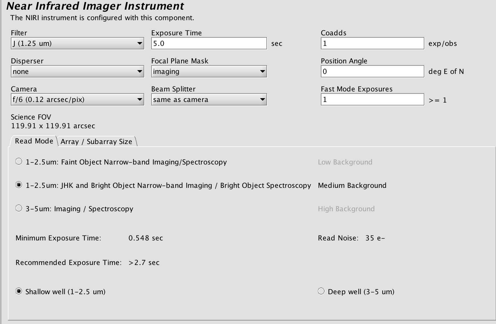
The detailed component editor for NIRI is accessed in the usual manner, by selecting the NIRI component in the science program, and is shown below:
Phase II (OT) Checklist
- Have you completed the General Gemini Phase II checklist?
Known Issues and Warnings
There are several things you should be aware of before you begin reducing your NIRI data. The NIRI detector has several problems/features and all frames should be carefully examined before including them in the final reduction, noting that some of these effects can only been seen after sky subtraction.
Spectroscopic Observing Strategies (Deprecated)
NOTE: Spectroscopic observing modes for NIRI have been decommissioned. The information in this section is provided solely to help users with the interpretation and reduction of archival spectroscopic NIRI data.
Calibrations
Near-IR calibrations are discussed in detail on the general near-IR web pages, as they are generally similar for all Gemini near-IR imagers and spectrographs. A baseline calibration set (not charged to the PI) is taken for each observation, generally the minimum calibrations necessary to ensure the utility of the observations in the archive.
Capability
Imaging
The properties of NIRI in imaging mode are summarized in the following sections. Three selectable fields of view and pixel scales are available. With adaptive optics NIRI is available at f/32 for J-L' imaging (but see caveats for L'), and at f/14 for imaging out to 2.5 microns due to the increased thermal background. Imaging at L' is impossible at f/6 and only sometimes possible at f/14.
Spectroscopy
Spectroscopy capability for NIRI has been decommissioned. The NIRI spectroscopy pages are provided for archival data reduction.
Low-moderate resolution spectroscopy could be obtained either at f/6 through each of the 1-5μm windows or at f/32 (the latter usually with adaptive optics) at JHK only. A variety of slit widths were available. The f/6 and f/32 pixel scales in spectroscopy mode were the same as those in imaging mode.
NIRI Sensitivity Tables
Without AO
The values in these tables are based on results from the NIRI Integration Time Calculator. They assume 70-percentile (IQ70, ~average) image quality for all categories, photometric conditions (CC50), and an airmass of less than 1.2 for the sensitivites presented here.
Guiding Options
Natural Seeing (Non-Adaptive Optics) Guided Observations:
NIRI standalone (i.e., without AO) requires the use of a peripheral wavefront sensor for both imaging and spectroscopy. PWFS2 is preferred over PWFS1, as it can be used on fainter guide stars, can run at a higher frequency for a given guide star, works better under windy and cloudy conditions, and is smaller and thus vignettes less of the field of view.
Proposals for Director’s Discretionary time for both Gemini North and South are not being accepted until at least 15 April 2020
Proposals for Director’s Discretionary time for both Gemini North and South are not being accepted until at least 15 April 2020.
Data reduction
This section describes the format of and some features associated with GNIRS data. More detailed information on reduction of GNIRS data accompanies the GNIRS IRAF package. GNIRS imaging can be reduced with the DRAGONS data reduction software.
Reducing XD spectra
This web page goes through the steps involved in reducing GNIRS cross-dispersed (XD) spectra using the Gemini IRAF package (v1.13.1). These spectra of a nearby galaxy nucleus were taken with the short (0.15 arcsec/pix) blue camera and 32 l/mm grating, the most commonly-used XD mode, but the data reduction steps will be broadly applicable to data taken in other XD configurations as well.
Exposure time estimation
Integration Time Calculator (ITC)
The GNIRS Integration Time Calculator (for spectroscopy only) can be used to determine limiting magnitudes, exposure times, S/N ratios, background levels, etc. for a wide range of source properties, observing conditions and GNIRS configurations. When using the ITC please note the caveats and guidelines at the top of the ITC web page.
Choosing optimal exposure times
This section gives information on the limitations to spectroscopic exposure times due to sky and telescope background and due to source signal. Acquisition exposure times are also provided in this section. The information can be used to determine optimal exposure times for science observations. Examples are given below the two tables.
Guideline Exposure Times for Standard Stars
Because spectra in the 1.0-2.5 micron region are often obtained in better conditions than those specified in Phase2, it is recommended that exposure times on standard stars be set conservatively. The exposure and coadd settings in the following table will provide high S/N in poor conditions without saturating the detector in good conditions. It is assumed that the observations consist of 1 ABBA sequence and are made at airmass 1.2.
Observation preparation
Learning the OT tool
In Phase II, is when you have to define concisely your observations; Phase II submissions are required to contain spectroscopic acquisition sequences and all calibrations. These observations are automatically generated by the Observing Tool (OT), although they will need customising for the PI's particular use case (e.g. adding telluric standard star coordinates).
Observing Strategies
This page brings together information that might affect decisions on observing strategy in various GNIRS observing modes, and provide guidelines/tips to maximize observing efficiency and avoid some common errors. The other GNIRS web pages (and especially the Known Issues page) also give information about what to expect from the instrument. For information about actually setting up observations in the Observing Tool, please see the Observation Preparation section of these pages.
Overheads
GNIRS observations incur overheads during the acquisition of the target and during the data taking.
Acquisitions
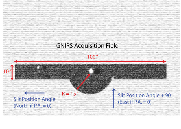
GNIRS contains a "flip" mirror that bypasses the dispersive optics (grating and prism) and provides a long and somewhat narrow acquisition field. This allows precise positioning of an object in a slit without moving the grating, prism, or camera. The choice of the acquisition filter is independent of the wavelength of the science observations.
Target acquisition is currently done in the following manner:
Phase II (OT) Checklist
There are many ways to check phase 2 files. However, for people new to GNIRS we suggest the following procedure. This assumes that the observations are set up using the OT automatic templates and/or following the templates in the OT library. NGO technical feasibility checks are carried out at the time of proposal submission, and we assume that problems with the proposed observing configuration/conditions have been sorted out by this point. For more information about GNIRS in the OT, see this section.
Known Issues and Warnings
The following are known problems or unwanted "features" associated with GNIRS
Calibrations
Baseline Calibrations
All calibrations, including tellurics, flatfields and arcs, must be specified in the Phase II definition. These "baseline" calibrations are summarized in the context of all Gemini Near-IR instrument calibrations (i.e. 1-5 µm imaging and spectroscopy).
Calibrations for GNIRS depends on the mode in which the instrument is configured, and can be summarized as follows:
Flat Field Info
The baseline default GNIRS flat fields that are obtained near-simultaneously with the science spectra are designed to provide higher signal-to-noise ratio (SNR) flat fields than the SNRs of typical science spectra, in modest amounts of time (a few minutes at most). They consist of a small number of individual flat field frames, which are summed by the user.
Arc Lamp Identifications
The following table shows a summary of GCAL emission line plots for two lamps (Ar and Xe) at near IR wavelengths. The spectra all have the same integration time. Wavelengths are in vacuum. See also the general wavelength calibration page for more line lists etc.
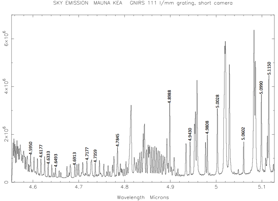
L band sky emission lines
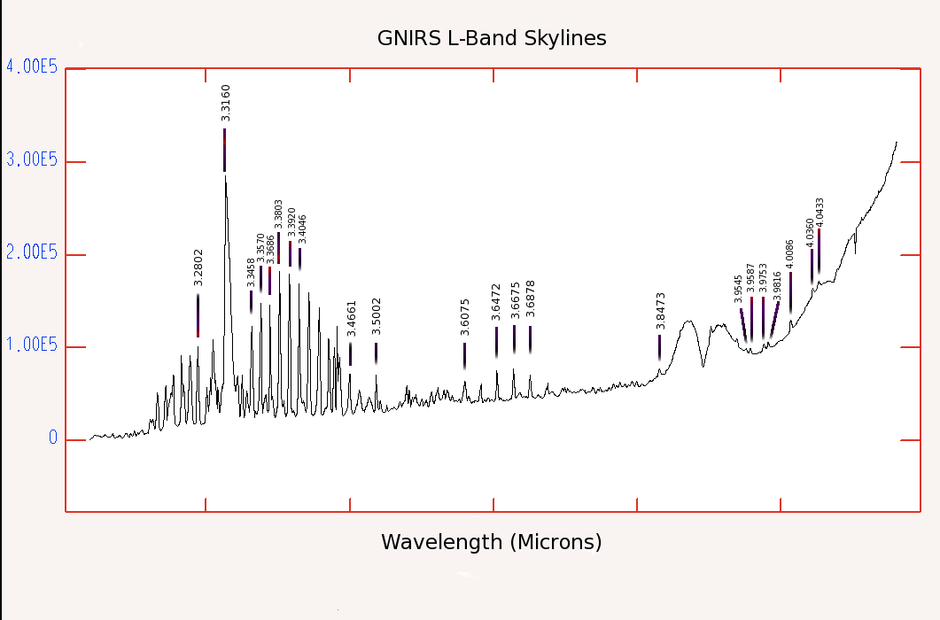
The following plot showing wavelengths of sky emission lines at 4.55-5.12 microns may be useful for wavelength calibration of GNIRS M band data. The data were taken using the 0.15"/pixel camera, 111 l/mm grating and 0.3" slit, and have R~4300.
M band sky lines
Components
Detector Array Properties and Read Modes
The properties of the Aladdin III InSb detector array for the GNIRS science channel are given in Table 1 below. The array has nicely uniform response, only a few regions of bad and dead pixels (see table below), very low dark current and low read noise in the lowest background mode. The bias voltage may be adjusted to increase the well depth for thermal IR (L and M band) observations or for very bright targets.
Order-blocking, Acquisition, and Neutral Density Filters
The filters listed below may be used for photometry on the Mauna Kea system. As they vignette the outer portions of the GNIRS acquisition keyhole, they should not be used for purposes of acquisition for spectroscopy.
Slit Properties
LR-IFU and HR-IFU Properties
The GNIRS Low and High Resolution IFUs are image slicers installed permanently in the GNIRS slit slide and they are therefore always available during GNIRS observing. They are inserted into the beam like a normal long slit, with light entering through a rectangular aperture at the front and leaving through a slit at the rear.
Gratings
The GNIRS grating turret contains three gratings (10, 32 and 110 l/mm), each with an effective first order blaze wavelength of 6.6 µm. The wavelength diffracted with peak efficiencies then correspond fairly well to the atmospheric windows centered at 5, 3.5, 2.2, 1.65, and 1.25 µm (M, L, K, H, J) for orders 1 through 5 respectively. The blocking filters used for these orders cover most or all of the free spectral ranges of the individual orders. A filter for order 6 (1.1 µm, called X) is also available.
Prisms and XD Spectroscopy
GNIRS contains two prisms designed to enable cross-dispersed spectroscopy in the 0.9-2.5 µm region. One, known as SXD, was designed for use with the short blue camera (0.15"/pix), and the other, known as LXD, for use with the long blue camera (0.05"/pix). The prisms disperse incident light in the direction orthogonal to that of the gratings, which allow grating orders 3-8 to appear at different locations on the array, as shown here.
Capability
Slit Spectroscopy
GNIRS has two basic slit spectroscopy modes.
Integral Field Spectroscopy
Low Resolution IFU
The LR-IFU takes a rectangular input field of 3.15" x 4.80" and split it in 21 slices of width 0.15". By re-arranging the slices end-to-end at the detector like a normal long-slit, the LR-IFU allows images to be dispersed into full-length spectra (covering one band, i.e., X, J, H, or K, with the short blue camera) while preserving the complete 2-D spatial information.
Imaging
GNIRS can be used for near-infrared (1.0-2.5µm + PAH at 3.3µm) imaging science and is in fact quite sensitive. However, as a photometer/imager it has the following limitations.
Guiding Options
GNIRS can be used with the standard Gemini peripheral wavefront sensors, or with the Altair adaptive optics module (in both natural and laser guide star modes).
Sensitivity
If you want to consult the monitoring of GNIRS sensitivity and throughput since 2011, please go here.